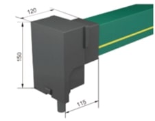
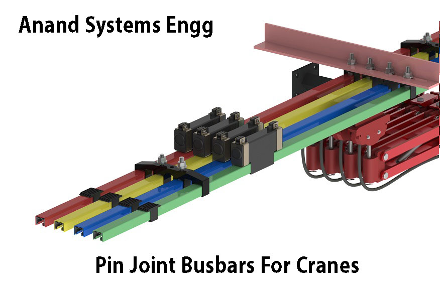
Center Power Feed
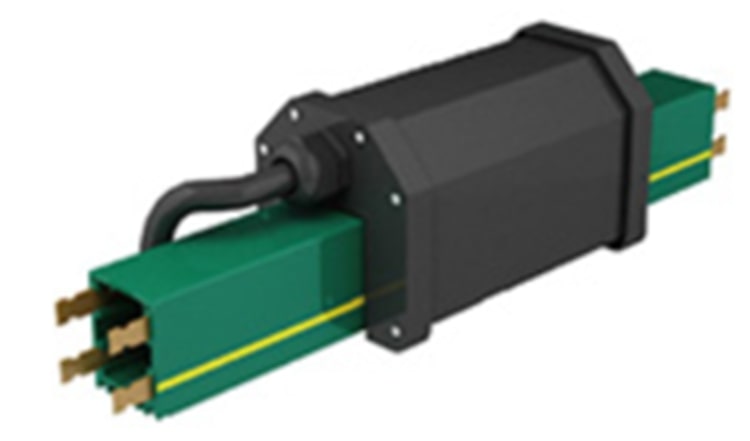
Copper - 40A,60A,80A,100A
120A,140A,160A

It is protected to IP23 standards. The conductor line in a rigid gray PVC housing with different copper cross sections for rated currents of 40Amp to 200Amp. The current collector running in ball bearing are guided by the housing. The main is transferred by spring-stored carbon brushes. A compact design, corrosion resistance and easy installation are the main characteristics.

For mobile power consumers like cranes, monorails, electrical hoists, conveyor systems, machines tools, automated storage, retrieval systems, lighting systems etc.


| Electrical properties: | Mechanical properties: | ||
|---|---|---|---|
| Max.current | 240A | Flexible strength | 75N/mm ±10% |
| Max.voltage | 660V | Tensile strength | 40N/mm ±10% |
| Dielectric strength | 30-40KV/mm | Temperature range: | |
| Spec.resistance | 5 x 10¹⁵ohm xcm | Standard Housing | -20C up to +70C |
| Surface resistivity | 1013ohm xcm | High Temp. Housing | -10C up to +115C |
| Leakage resistance | CTI600-2.7 | Low Temp. Housing | -40C up to +80C |
| Combustibility: | |||
| Flame retardant | B1 | ||
| Self extinguishing | Class B1-no flaming particles,self-extinguishing | ||
| Resistance to chemicals: +45C | |||
| Gasoline | Sulphuric acid 50 % | ||
| Mineral Oil | Caustic Soda25% and 50% | ||
| Grease | Hydro-chloric acid, concentrated | ||
Consider the voltage drop calculation to maintain the limits established by the motor manufacturers!
| Formulas: | Effective length: | ||
|---|---|---|---|
| AC: | U = v3 x I x l x Z |
l = L | power feed located at the end of the system |
| DC: | U1 = 2l x I x R |
l = L/2 | power feed located at the center of the system |
U2 = (U1 100) / V |
l = L/4 | power feed located at both ends of the system | |
| l = L/6 | power feed located at L/6 from each end of the system | ||
|
|||
The total ampere load is determined from the nominal rated current of all motors working simultaneously on the same feed section of your electrification system. A diversity factor of 0,5-0,9 can be considered.
The conductor size and/or number of feed points should be increased or booster cables should be used in parallel in case the drop is exceeding the limitations.
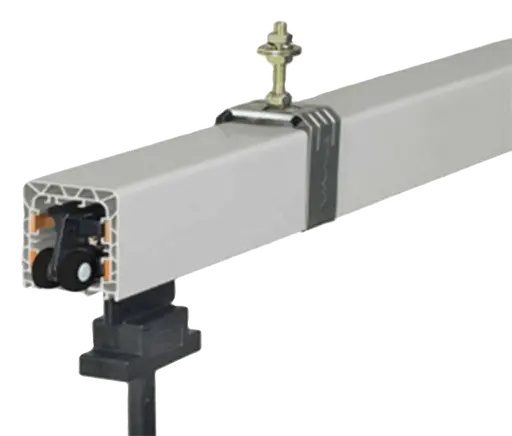
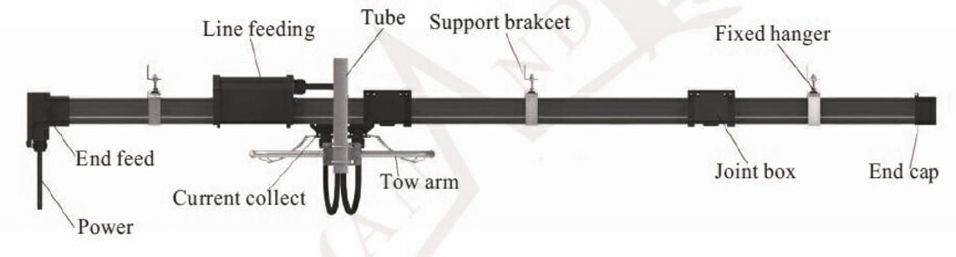
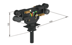
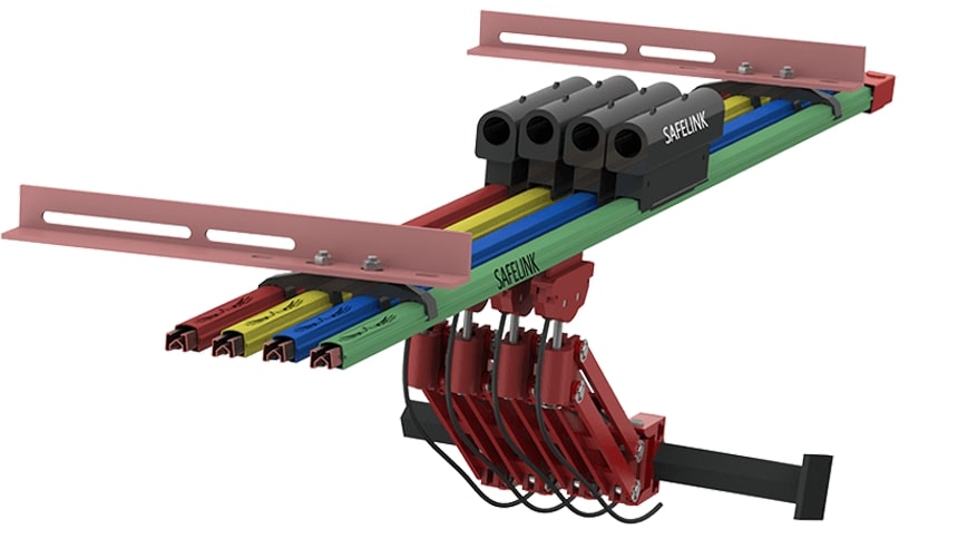
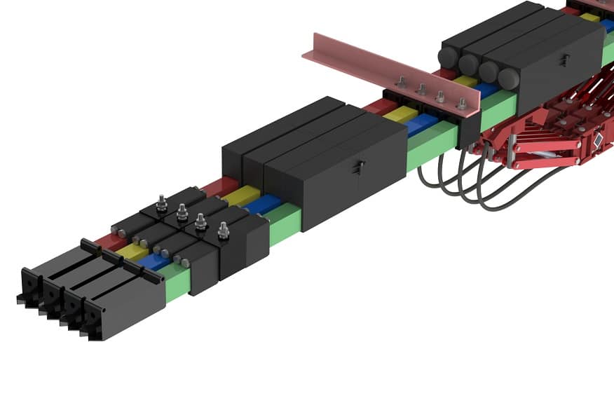
The current collectors are made of re-inforced polyester fiberglass, for high strength and light weight. Spring loaded carbon brushes maintain uniform contact. Connecting cables and hinged or flexible towing arms included double collectors for transfer applications and higher amperage
Grey color, plastic housing, 4 Mtr standard section. The ground conductors is identified by international color code. Phase reversing prevented by design of the collector and housing.Higher number of conductors possible by combination of several enclosed conductor line.

The open ends of the enclosed conductor are closed by end caps.
Line feeds or end feeds.
Easy Maintenance Busbar, upto 315 Amps
Copper & Aluminium Busbars, upto 1250Amps
Copper & GI Busbars, upto 315 Amps