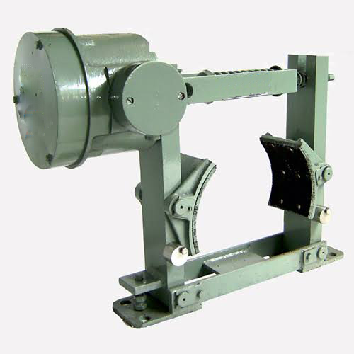
DC ElectroMagnetic brake
DC Electro magnetic Brakes are used when a load must be stopped rapidly to prevent the load from rotating.
Electromagnetic Brakes are manufactured in Drum Diameters: 100 mm - 800 mm

Direct Current Electromagnetic Brakes for any Crane
"ANAND SYSTEM" are the pioneers of the Indian Crane Control gear Industry. With experience in this field for more than 25 years they offer you their most comprehensive range of industrial brakes already being used by various crane and machinery manufacturers.
DC Electromagnetic brake product description
"ANAND SYSTEMS" mill duty D.C Electro magnetic Brake are suitable for 220V D.C supply for wide range of drum sizes from 100mm to 800mm.
Electro magnetic Brakes are used when a load must be stopped rapidly to prevent the load from rotating due to the motor and load inertia
at a select a pre-determined time or at selected points of travel or to prevent over travelling.
Calculated Size of the AC EM Brake
To calculate the size of "ANAND SYSTEM" Electro magnetic Brake for a given application it is necessary to take into consideration the H.P.
Rating and speed in R.P.M. to obtain the required retarding torque. The basic formula against which calculations are made is :
Torque in Kg.M. = (71620 x H.P.) / (Speed in R.P.M. x 100)
OR
= (975 x KW) / RPM
To obtain maximum efficiency the Brake should be mounted directly on the motor shaft.
The application involving ardous duty with more self-sustaining load characteristic such as hoist motions of Electric Crane hoists,
skip hoist equipment, overload factor must be taken into consideration. In applications of this nature it is usual to
assess the Brake torque required on the basis of 150-175% full load torque.
SALIENT FEATURES
A) The mill duty brakes are superior in construction to the usual heavy duty E.M Brakes as the base is of fabricated construction,
the arms are cast steel or fabricated construction. The pins are of hardened steel and lubrication is provided for brakes of 400 mm dia
and above as a rule.
B) The brake shoes are designed for 70deg angle which is in accordance with modern practice and this makes it easy for replacement of
brake shoe without any major dismantling.
C) The coils are either class "F" or "H" and are liberally designed to allow for high ambient temperature prevailing in the steel plants.
D) The magnet housing is of dust proof construction and the magnet system is of quick acting type which is achieved by use of economy
resistor and the forcing contactor. This enables the brake to operate on very high frequency of operation (600 to 720 per hour)
E) Mill duty D.C Electro magnetic Brakes are manufactured in a wide range of Drum dia-meters from 100mm upto 800mm preferred series
and standard metric size dia meters are available. The torque range available in this series is from 200kg CM (for the smaller brake )
upto 125,000 kg CM (for the largest brake). These torques correspond to 25% intermittent duty which is applicable to most of medium duty
cranes of steel plants. The rating of 40% and 100% duty cycle are also given in the charts.
Operation
a) On energizing the coil , the operating magnet releases the brake and on deenergizing the powerful spring which sets the brake
acts up on the brake shoes through the brake arms. The magnet armature is an integral part of one shoe arm whilst the other arm is
directly coupled to the magnet filed member by means of a steel tie-rod which passes through the spring and over the brake wheels.
b) The heavy coil spring exerts rapid and steady force on the brake shoes and breakdrum through the arms and maximum stress is well
within safe limits. Equal travel and balanced movement on both shoes applies even and positive torque in either direction of rotation.
c)Because the movement is almost directly exerted on the brake shoes , the magnet designed for the short stroke, with small air gap and very
high electro-magnetic efficiency .Since the total movement generally responds to clearances between brake shoes and brake wheel, this takes
place with remarkable speed and with smooth, quite action in.
d) Installation is easy and routine adjustment are few. Braking torque is set correctly at installation and requires no major adjustment
except when shoe/linings are renewed.
Electro Magnet
Brake magnets are series-wound ot shunt-wound according to the service for which the brakes are to be used.
If the nature of work is such that brake action must be independent of the motor a shunt wound brake is necessary.
The action of a series-wound brake depends directly upon the current taken by the driving d.c motor.
For shunt-wound brake operating on 220volts D.C a series resistor (economy resistor) is supplied with each brake in the coil is
energized on full voltage (220V) so as to ensure the quick opening (release) of the brake after which the economy resistor is
introduced into circuit by a timer/contactor arrangement which is an integral part of the rectifier unit.
Sufficient force would still be developed by the magnet to hold the brake in open (released) position and at the same
time the heating of the brake coil is greatly reduced.
This ensure that coil operates well within the temperature limits for the type of insulation used and gives long life and reliability .
The coils are designed to operate at 85% to 110% of the rated voltage , which is the normal practice for all control gear.
The maximum braking torque specified in the rating chart correspond to the 25% intermittent duty i,e total "on" time of 2.5
minutes in maximum cycle of 10 minutes which can be repeated indefinitely.
The brake coils and economy resistor are matched suitably to give the desired performance at the specified intermittent duty factor.
Product List of Drum
| Sr. no. | Product Name | Description | Part Number | Images |
|---|---|---|---|---|
| 1 | CAST IRON BRAKE DRUM DRUM 100 DIA | DRUM 100 DIA | CI-Brake-Drum-100 | |
| 2 | CAST IRON BRAKE DRUM DRUM 150 DIA | DRUM 150 DIA | CI-Brake-Drum-150 | |
| 3 | CAST IRON BRAKE DRUM DRUM 160 DIA | DRUM 160 DIA | CI-Brake-Drum-160 | |
| 4 | CAST IRON BRAKE DRUM DRUM 200 DIA | DRUM 200 DIA | CI-Brake-Drum-200 | |
| 5 | CAST IRON BRAKE DRUM DRUM 250 DIA | DRUM 250 DIA | CI-Brake-Drum-250 | |
| 6 | CAST IRON BRAKE DRUM DRUM 300 DIA | DRUM 300 DIA | CI-Brake-Drum-300 | |
| 7 | CAST IRON BRAKE DRUM DRUM 400 DIA | DRUM 400 DIA | CI-Brake-Drum-400 | |
| 8 | CAST STEEL BRAKE DRUM DRUM 100 DIA | DRUM 100 DIA | CS-Brake-Drum-100 | |
| 9 | CAST STEEL BRAKE DRUM DRUM 150 DIA | DRUM 150 DIA | CS-Brake-Drum-150 | |
| 10 | CAST STEEL BRAKE DRUM DRUM 160 DIA | DRUM 160 DIA | CS-Brake-Drum-160 | |
| 11 | CAST STEEL BRAKE DRUM DRUM 200 DIA | DRUM 200 DIA | CS-Brake-Drum-200 | |
| 12 | CAST STEEL BRAKE DRUM DRUM 250 DIA | DRUM 250 DIA | CS-Brake-Drum-250 | |
| 13 | CAST STEEL BRAKE DRUM DRUM 300 DIA | DRUM 300 DIA | CS-Brake-Drum-300 | |
| 14 | CAST STEEL BRAKE DRUM DRUM 400 DIA | DRUM 400 DIA | CS-Brake-Drum-400 | |
| 15 | DRUM WITH COUPLING C.I. Drum With Coupling 100 DIA | DRUM WITH COUPLING C.I. | CIBDC 100 TO 400 | |
| 16 | DRUM WITH COUPLING C.I. Drum With Coupling 100 DIA | Drum With Coupling 100 DIA | CI-Brake-Drum-100-Coupling | |
| 17 | DRUM WITH COUPLING C.I. Drum With Coupling 150 DIA | Drum With Coupling 150 DIA | CI-Brake-Drum-150-Coupling | |
| 18 | DRUM WITH COUPLING C.I. Drum With Coupling 160 DIA | Drum With Coupling 160 DIA | CI-Brake-Drum-160-Coupling | |
| 19 | DRUM WITH COUPLING C.I. Drum With Coupling 200 DIA | Drum With Coupling 200 DIA | CI-Brake-Drum-200-Coupling | |
| 20 | DRUM WITH COUPLING C.I. Drum With Coupling 250 DIA | Drum With Coupling 250 DIA | CI-Brake-Drum-250-Coupling | |
| 21 | DRUM WITH COUPLING C.I. Drum With Coupling 300 DIA | Drum With Coupling 300 DIA | CI-Brake-Drum-300-Coupling | |
| 22 | DRUM WITH COUPLING C.I. Drum With Coupling 400 DIA | Drum With Coupling 400 DIA | CI-Brake-Drum-400-Coupling | |
Torque rating of Anand Systems Mill Duty D.C Brakes
100mm to 800mm.
| Brake Type | Drum Diameter(mm) | Duty Cycle | Maximum Braking Torque Kg. Cm. | Minimum Braking Torque Kg. Cm. | |
|---|---|---|---|---|---|
| DCM 100 | 50% | 100% | 50% | 100% | |
| DCM 150/160 | 57 | 2.20 | 1.87 | 3 | 2.5 |
| DCM 200 | 70 | 7.6 | 6.5 | 10 | 9.0 |
| DCM 250 | 89 | 17.75 | 15 | 24 | 20 |
| DCM 300/315 | 108 | 22.70 | 19.3 | 30 | 35 |
| DCM 400 | 127 | 45.7 | 38.80 | 60 | 50 |
| DCM 500 | 152 | 69.00 | 58.6 | 95 | 80.0 |