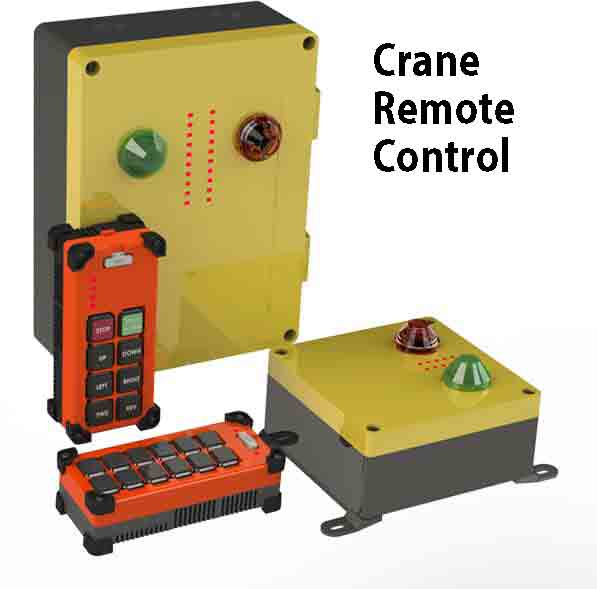
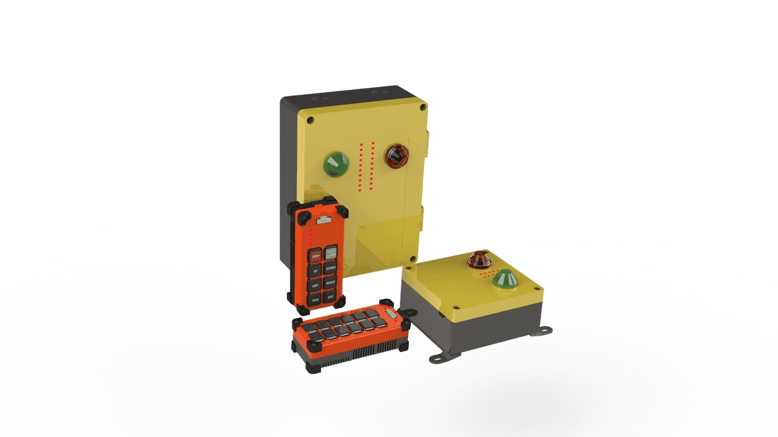
Wireless Radio Remote Controls
Artificially generated radio waves are used to control any type of machinery or equipment wirelessly,such kind of a control system is called a Radio Remote Control.
A Blog on Radio Technology
Content
- 4. How Radio Technology Works?
- a. Antenna
- b. Impedance Matching of Antenna
- c. Transmission Line
- d. Low Noise Amplifier
- e. PLL
What are Radio Waves?
Each Object that we see with our eyes reflect light .
This visible Light travelling through space is vibrating at a particular frequency is called an electromagnetic wave .
The complete electoro magnetic spectrum consists of waves vibrating at different frequencies .
Electromagnetic waves in the frequency range of 10khz upto 300Ghz are categorized as Radio Waves and Micro Waves.
At these frequencies Alternating current in a conductor can emit energy into free space as radio waves.
Radio waves don't require a medium to move as required by Sound waves.They are a naturally emitted by Stars,
Other electromagnetic waves such as X-rays, Gamma Rays ,Visible Light only differ from radio waves in terms
of frequency and wavelength.
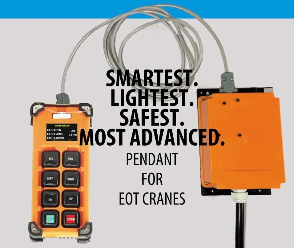
2. What are Radio Remote Controls?
When artificially generated radio waves are used to control any type of machinery or equipment wirelessly,
such kind of a control system is called a Radio Remote Control.
It typically consists of a transmitter device which radiates data in the form of a radio wave in free space with the help
of an antenna towards the receiver. The receiver then picks up this signal with an antenna and decodes the data.
Radio remote controls are completely wireless systems which can transmit and receive data over very long distances.
Need for radio remote controls
Typical radio remote control applications are
-
Mobile phones for voice transmission
-
Bluetooth devices
-
Wi-Fi for providing internet over radio
-
Walkie Talkie systems
-
Songs over (Frequency Modulated)FM Radio and AM (Amplitude Modulated) Radio
-
Satellite communication
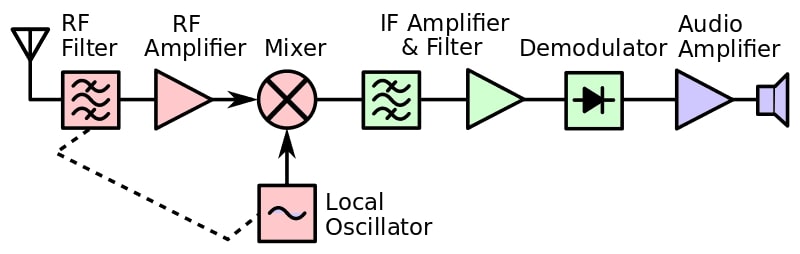
How Radio Technology Works?
Signal Received or transmitted by Antenna
Once the antenna has picked up the signal ,a band pass filter only allows the desired frequencies to pass while
attenuating other frequencies .
Since many different radio waves are traveling through air at a given point of time, the antenna must be tuned to
receive waves at the required frequency.
For example , an antenna tuned to 2.4ghz frequency will have a very low return loss at 2.4ghz and will exhibit a
very high return loss at other frequencies .
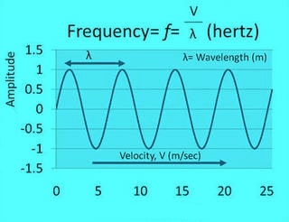
For a monopole or Dipole Antenna, the length of the antenna depends on the wavelength of the desired frequency.
λ = c/f
λ = wavelength
C = Speed of light
F = desired frequency
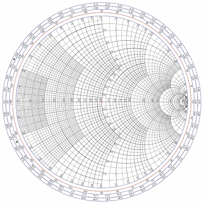
Impedance Matching of Antenna
A quarter wave monopole antenna has an input impedance of approximately 37 ohms whereas a dipole antenna has a
characteristic impedance of 73 ohms.
These antennas can be matched to the transmission line with a PI
filter or T Filter using a Smith Chart.
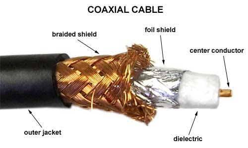
Transmission Line
When a signal is received by the antenna for which it is tuned, it is passed on to the Low Noise Amplifier(LNA)
through the transmission line.The transmission line connects the antenna to the receiver or transmitter.
This transmission line can be a 50 ohm characteristic impedance coaxial cable or trace on the pcb circuit.
The 50 ohm characteristic impedance of the transmission line must match the input impedance of antenna for maximum power delivery.
Since, nothing is ideal in this world, the signal will lose its power while travelling through the transmission line.
Low Noise Amplifier
After the band pass filter , the signals need to be amplified with the help of a low noise power amplifier.
It applies gain to the signal ,but also applies the same amount of gain to the noise within the signals.
The LNA must apply gain in the frequency spectrum of interest.
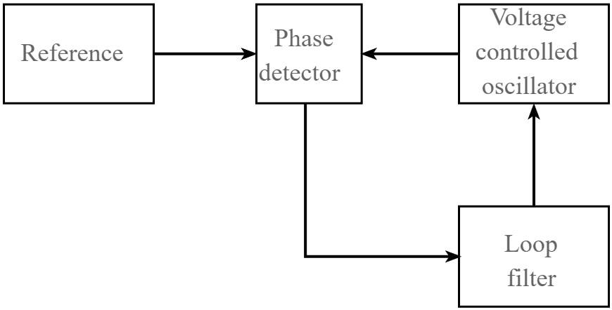
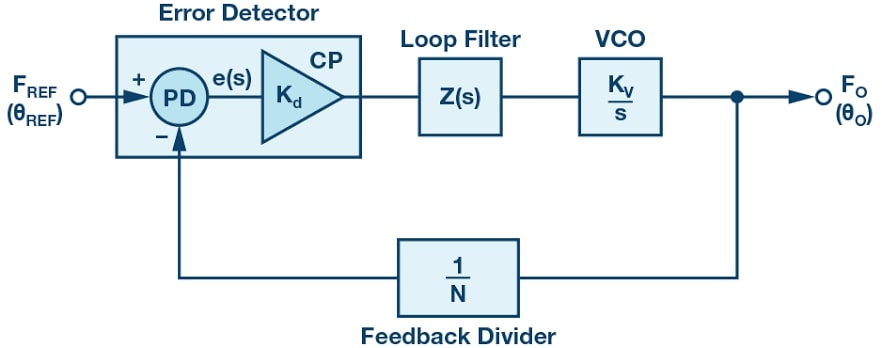
Phase Locked Loop (PLL):
PLL application in receiver:
As the receiver circuit needs to get a lock on the transmitted signals a PLL is used.
First the PLL is not locked to the desired frequency so,the Phase comparator Compares the difference in phase
between the input frequency received by the antenna to the internal Oscillator reference frequency and gives the
error signal to the Loop Filter.
Voltage controlled Oscillator then receives the error signal and changes it frequency until the error becomes zero.
When the error is zero between the phase of the reference as well as the oscillator frequency is in lock.
PLL application in Transmitter:
Since high frequencies are difficult to process , in a transmitter circuit a phase-locked loop allows stable high frequencies to be generated from a low Intermediate frequency reference. Any system that requires stable high frequency tuning can benefit from the PLL technique.
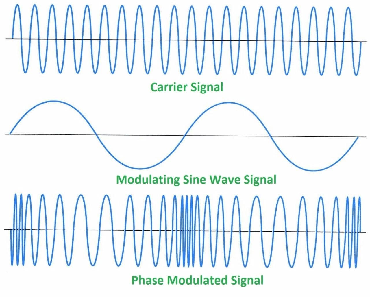
Modulation techniques
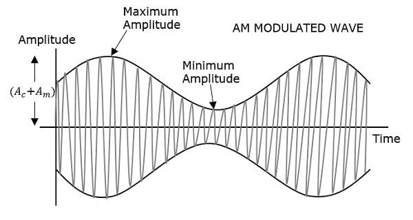
Amplitude Modulation:
Data can be modulated onto the carrier wave by changing the Amplitude of the signal according to the data
to be sent.But there are many disadvantages to using Amplitude modulation such as low power efficiency, high noise
Voltage controlled Oscillator then receives the error signal and changes it frequency until the error becomes zero.
When the error is zero between the phase of the reference as well as the oscillator frequency is in lock.
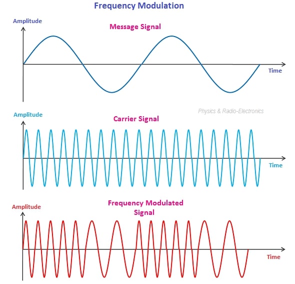
Frequency Modulation:
Data can be modulated onto the carrier wave by changing the frequency of the carrier wave according to the data to be sent.
For example if the carrier frequency is 866Mhz and we want to transmit a Data bit 0 . We increase the frequency by 40khz.
If we want to transmit Data bit 1, we decrease the frequency by 40khz. This deviation of frequency from the carrier
frequency is called frequency modulation.Frequency modulation is easier to modulate and demodulate than phase Modulation
Phase Modulation:
Data can be modulated onto the carrier wave by changing the phase of the carrier wave according to the data to be sent.
Noise Immunity
When using any radio frequency spectrum the manufacturer has to realize that many other radio systems from other manufacturers and individuals might be using the same frequencies for transmissions. Hence, many radio systems need to operate in very noisy rf environments successfully. This problem of coexistence is solved by using spread spectrum technologies such as Frequency Hopping Spread Spectrum and / or Direct Sequence Spread Spectrum (DSSS).
Spread Spectrum Technologies to Improve Noise Immunity
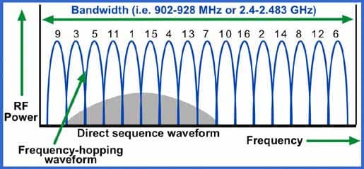
Frequency Hopping Spread Spectrum
Direct Sequence Spread Sprectrum
FHSS Combined with DSSS
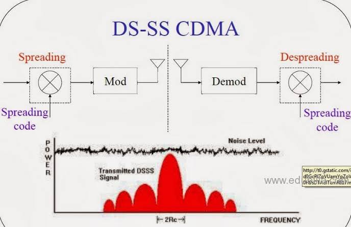
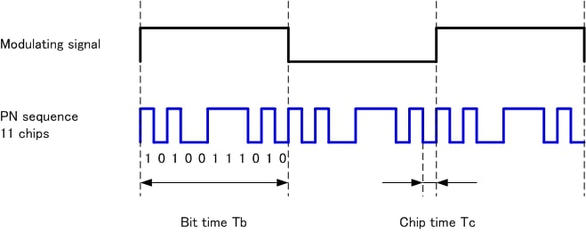
Direct Sequence Spread Spectrum
DSSS is a spread spectrum technology which XORs the data signal over the frequency spectrum by using a
sequence of chipping code . The number of bits to be transmitted is now more than the data itself due to the XOR operation.
This whole modified data stream is now modulated onto the carrier wave using amplitude ,frequency or phase modulation and
transmitted via the antenna.
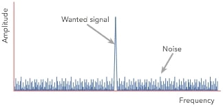
To the receiver which does not have this chipping code, the data signal will appear as white noise in the frequency spectrum
of interest.
If the receiver has the correct chipping sequence , it can recover the whole data stream , and extract the required data
after demodulation.
This helps to improve noise immunity as the transmitted signal is spread over a bigger bandwidth with a chipping code
only known to the transmitter and the receiver
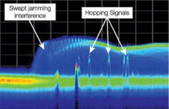
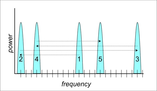
Frequency Hopping Spread Spectrum
Frequency hopping Spread spectrum is a spreading technology where the carrier wave of the data to be transmitted is changed
frequently according to a Pseudo Random sequence known to the transmitter and the receiver.
Once the transmitter and receiver are synchronized , the transmitter will hop between a known sequence of carrier frequencies
to transmit the data , since this hopping sequence is known to the receiver , the receiver will listen on the frequencies
in the order that was predetermined.
So a noise Interference on one frequency will not affect the data transmission as the carrier frequency will be changed.
This makes the transmission more secure to hacking as well as noise.This also helps in co existence of multi radio
transmitters and receiver systems as all of the systems will continuously hop to a different pseudo random frequency
after a transmission.
Frequency hopping combined with DSSS
With the combined advantages of frequency hopping spread spectrum & direct sequence spread spectrum this combined method proves to take noise immunity,co existance & channel security to whole new level.A noise signal or a hacker will have to trace the psuedo random hopping frequencies as well as the psuedo random chipping sequence of the DSSS signal.At the added cost of software complexity , this combined system far outshines both the individual systems alone.